Pages

Search This Blog

Friday 26 July 2013

Neutral Section


Neutral Section Indication Board used on railways in the UK
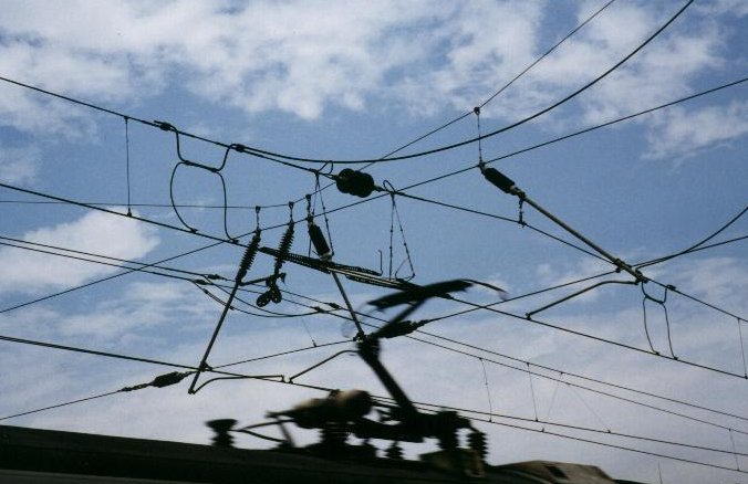
To allow maintenance to sections of the overhead line without having to turn off the entire system, the overhead line system is broken into electrically separated portions known as sections. Sections often correspond with tension lengths as described above. The transition from section to section is known as a section break and is set up so that the locomotive's pantograph is in continuous contact with the wire.
For bow collectors and pantographs, this is done by having two contact wires run next to each other over a length about four wire supports: a new one dropping down and the old one rising up until the pantograph smoothly transfers from one to the next. The two wires never touch (although the bow collector/pantograph is briefly in contact with both wires). In normal service, the two sections are electrically connected (to different substations if at or near the halfway mark between them) but this can be broken for servicing.
On overhead wires designed for trolley poles this is done by having a neutral section between the wires, requiring an insulator. The driver of the tram or trolleybus must turn off the power when the trolley pole passes through, to prevent arc damage to the insulator.
Sometimes on a larger electrified railway, tramway or trolleybus system, it is necessary to power different areas of track from different power grids, the synchronisation of the phases of which cannot be guaranteed. (Sometimes the sections are powered with different voltages or frequencies.) There may be mechanisms for having the grids synchronised on a normal basis but events may cause desynchronisation. This is no problem for DC systems but, for AC systems, it is highly undesirable to connect two unsynchronised grids. A normal section break is insufficient to guard against this, since the pantograph briefly connects both sections.
Instead, a phase break or neutral section is used. This consists of two section breaks back-to-back so that there is a short section of overhead line that belongs to neither grid. If the two grids are synchronized, this stretch of line is energized (by either supply) and trains run through it normally. If the two supplies are not synchronized, the short isolating section is disconnected from the supplies, leaving it electrically dead, ensuring that the two grids cannot be connected to each other.


The sudden loss of power over the phase break would jar the train if the locomotive was at full throttle, so special signals are set up to warn the crew. When synchronization is lost and

the phase break is deenergized, the train's operator must put the controller (throttle) into neutral and coast through an isolated phase break section.
On the Pennsylvania Railroad, phase breaks were indicated to train crews by a metal sign hung from the overhead with the letters PB on it, created by drilled holes. When the phase break was "dead", a signal with eight lights in a circular pattern indicated so.
Transnet Freight Rail in South Africa has permanent magnets between the rails at both sides of the neutral section where two phases are separated. These are detected by equipment on the locomotive, which disconnect and reconnect power from the pantographs.


The neutral section used in mumbai is between kalyan-shahad and kalyan-vitthalwadi to seperate the AC and DC line. Before Kalyan towards CST DC overhead line is used and after kalyan towards khopoli and kasara AC overhead line is used so between them the neutral section is provided to seperate the AC and DC lines.

Pantograph

http://upload.wikimedia.org/wikipedia/commons/d/d4/Button_hide.png


A pantograph is a device that collects electric current from overhead lines for electric trains or trams. The term stems from the resemblance to pantograph devices for copying writing and drawings.
A flat side-pantograph was invented 1895 at the Baltimore & Ohio Railroad and in Germany 1900 by Siemens & Halske.
According to the late rail historian Harre Demoro, the pantograph was invented by the Key System shops for their commuter trains in the East Bay section of the San Francisco Bay Area in California. They appear in photographs of the first day of service in 1903. For many decades thereafter, the same diamond shape was used by electric rail systems around the world, and remains in use by some today.
However, the most common type today is the so called half-pantograph (sometimes 'Z'-shaped), which has evolved to provide a more compact and responsive single arm design at high speeds as trains get faster. The half-pantograph can be seen in use on everything from the very fastest trains such as the TGV to low-speed urban tram systems. The design operates with equal efficiency in either direction of motion, as demonstrated by the Swiss and Austrian railways whose newest high performance locomotives, the Re 460 and Taurus respectively, operate with them set in opposite directions.
The electric transmission system for modern electric rail systems consists of an upper load carrying wire (known as a catenary) from which is suspended a contact wire. The pantograph is spring loaded and pushes a contact shoe up against the contact wire to draw the electricity needed to run the train. The steel rails on the tracks act as the electrical return.
As the train moves, the contact shoe slides along the wire and can set up acoustical standing waves in the wires which break the contact and degrade current collection. This means that on some systems adjacent pantographs are not permitted. Pantographs are the successor technology to trolley poles, which were widely used on early streetcar systems

and still are used by trolleybuses, whose freedom of movement and need for a two-wire circuit makes pantographs impractical.
Pantographs with overhead wires are now the dominant form of current collection for modern electric trains because, although more expensive and fragile than a third-rail system, they allow the use of higher voltages.
              Pantographs easily adapt to various heights of the overhead wires by partly folding. The tram line pictured here runs in Vienna.
The electric transmission system for modern electric rail systems consists of an upper weight carrying wire (known as a catenary) from which is suspended a contact wire. The pantograph is spring loaded and pushes a contact shoe up against the contact wire to draw the electricity needed to run the train. The steel rails on the tracks act as the electrical return.
As the train moves, the contact shoe slides along the wire and can set up acoustical standing waves in the wires which break the contact and degrade current collection. This means that on some systems adjacent pantographs are not permitted. Pantographs are the successor technology to trolley poles, which were widely used on early streetcar systems and still are used by trolleybuses, whose freedom of movement and need for a two-wire circuit makes pantographs impractical.
Pantographs with overhead wires are now the dominant form of current collection for modern electric trains because, although more expensive and fragile than a third-rail system, they allow the use of higher voltages.

Pantographs are typically operated by compressed air from the vehicle's braking system, either to raise the unit and hold it against the conductor or, when springs are used to affect the extension, to lower it. As a precaution against loss of pressure in the second case, the arm is held in the down position by a catch. For high-voltage systems, the same air supply is used to "blow out" the electric arc when roof-mounted circuit breakers are used. 

Overhead Equipment


OVERHEAD EQUIPMENT

Catenary and Contact Wires

1. The overhead equipment above the track comprises of the following:-
a) A stranded cadmium copper wire of about 65 mm2 section or stranded aluminium alloy wire of about 116 mm2 section for catenary.
b) A grooved hard drawn copper contact wire of 107 mm2 cross-section (when new) supported from the catenary by means of droppers of 5 mm diameter spaced not more than 9 m apart.
2. The catenary and contact wire together have an equivalent copper section of 157 mm2. The current normally permissible on a single track is 600 A approximately, because of equivalent cross-sectional area of OHE. This current limit is based on the temperature limit of 85C in contact wire. Certain sections in Waltair-Kirandul section have the catenary and contact wires together having an equivalent copper section of 200 mm2.
3. For loop lines, sidings, yards and spur lines excluding the main running lines and first loop or lines taking off from main running line, tramway type OHE having only grooved hard drawn copper contact wire of 107 mm2 section is provided.

Height of Contact Wire

The normal height of contact wire for regulated OHE is 5.60 m above rail level. For unregulated OHE in areas with a temperature range of 4C
to 65 C, and in areas with a temperature range of 15 C to 65 C, it is 5.65 m. In certain cases, such as under over-line structures, the height may be as low as 4.65 m on BG and 4.02 m on MG.

 Span of Supporting Mast/Structures

The span normally used for supporting the OHE from masts/structure using the cantilever type bracket assembly varies from maximum 72 m on straight track to 27 m on curved track, the spans depending upon the degree of curvature. The

catenary system is normally supported on straight tracks at maximum intervals of 72 m (63 m on MG) by cantilever type arms fixed to galvanized broad flange or I section steel masts or fabricated steel structures. On curves the catenary is supported at closer intervals, the spans adopted depending upon the degree of curvature.

Stagger

The contact wire is staggered so that as the pantograph glides along, the contact wire sweeps across the current collecting strips of the pantograph upto a distance of 200 mm on either side of the centre line on straight runs and 300 mm on one side on curves.

Regulated and Unregulated OHE

OHE with automatic tensioning called 'regulated OHE' is generally provided for all main lines, but for large isolated yard and unimportant lines, automatic tensioning is dispensed with in the interest of economy and only unregulated OHE is used.


Compressor


Passing Gas
A look at how different compressors work;

Most cooling systems, from residential air conditioners to large commercial and industrial chillers, employ the refrigeration process known as the vapour compression cycle. At the heart of the vapour compression cycle is the mechanical compressor. A compressor has two main functions: 1) to pump refrigerant through the cooling system and 2) to compress gaseous refrigerant in the system so that it can be condensed to liquid and absorb heat from the air or water that is being cooled or chilled (See the "How it Works" section of the article "Gas Engine Chillers" for an explanation of the vapour compression cycle).
There are many ways to compress a gas. As such, many different types of compressors have been invented over the years. Each type utilizes a specific and sometimes downright ingenious method to pressurize refrigerant vapour. The five types of compressors used in vapour compression systems are Reciprocating, Rotary, Centrifugal, Screw and Scroll.


Reciprocating Compressors
A reciprocating compressor uses the reciprocating action of a piston inside a cylinder to compress refrigerant. As the piston moves downward, a vacuum is created inside the cylinder. Because the pressure above the intake valve is greater than the pressure below it, the intake valve is forced open and refrigerant is sucked into the cylinder. After the piston reaches its bottom position it begins to move upward. The intake valve closes, trapping the refrigerant inside the cylinder. As the piston continues to move upward it compresses the refrigerant, increasing its pressure. At a certain point the pressure exerted by the refrigerant forces the exhaust valve to open and the compressed refrigerant flows out of the cylinder. Once the piston reaches it top-most position, it starts moving downward again and the cycle is repeated.


Rotary Compressors
In a rotary compressor the refrigerant is compressed by the rotating action of a roller inside a cylinder. The roller rotates eccentrically (off-centre) around a shaft so that part of the roller is always in contact with the inside wall of the cylinder. A spring-mounted blade is always rubbing against the roller. The two points of contact create two sealed areas of continuously variable volume inside the cylinder. At a certain point in the rotation of the roller, the intake port is exposed and a quantity of refrigerant is sucked into the cylinder, filling one of the sealed areas. As the roller continues to rotate the volume of the area the refrigerant occupies is reduced and the refrigerant is compressed. When the exhaust valve is exposed, the high-pressure refrigerant forces the exhaust valve to open and the refrigerant is released. Rotary compressors are very efficient because the actions of taking in refrigerant and compressing refrigerant occur simultaneously.


Catenary


Overhead lines

Two overhead conductor rails for the same track. Left, 1,200 V DC for the Uetliberg railway (the pantograph is mounted asymmetrically to collect current from this rail); right, 15 kV AC for the Sihltal railway.
Overhead lines or overhead wires are used to transmit electrical energy to trams, trolleybuses or trains at a distance from the energy supply point. These overhead lines are known variously as;
·                     Overhead contact system (OCS)—Europe, except UK and Spain
·                     Overhead line equipment (OLE or OHLE)—UK
·                     Overhead wiring (OHW)—Australia
·                     Catenary—United States, UK, Singapore (North East MRT Line), Canada and Spain.

Overview

Electric trains that collect their current from an overhead line system use a device such as a pantograph, bow collector, or trolley pole. The device presses against the underside of the lowest wire of an overhead line system, the contact wire. The current collectors are electrically conductive and allow current to flow through to the train or tram and back to the feeder station through the steel wheels on one or both running rails. Non-electric trains (such as diesels) may pass along these tracks without affecting the overhead line, although there may be difficulties with overhead clearance. Alternative electrical power transmission schemes for trains include third rail, batteries, and electromagnetic induction.

Construction

To achieve good high-speed current collection it is necessary to keep the contact wire geometry within defined limits. This is usually achieved by supporting the contact wire from above by a second wire known as the messenger wire (UK) or catenary (US & Canada). This wire is allowed to follow the natural path of a wire strung between two points, a catenary curve, thus the use of catenary to describe this wire or sometimes the whole system. This wire is attached to the contact wire at regular intervals by vertical wires known as droppers or drop wires. The messenger wire is supported regularly at structures, by a pulley, link, or clamp. The whole system is then subjected to a mechanical tension.
As the contact wire makes contact with the pantograph, the carbon surface of the insert on top of the pantograph is worn down. Going around a curve, the "straight" wire between supports will cause the contact wire to cross over the whole surface of the pantograph as the train travels around the curve, causing an even wear and avoiding any notches. On straight track, the contact wire is zigzagged slightly to the left and right of centre at each successive support so that the pantograph wears evenly.
The zigzagging of the overhead line is not required for trolley-based trams or trolleybuses.
Depot areas tend to have only a single wire and are known as simple equipment. When overhead line systems were first conceived, good current collection was possible only at low speeds, using a single wire. To enable higher speeds, two additional types of equipment were developed:
·                     Stitched equipment uses an additional wire at each support structure, terminated on either side of the messenger wire.
·                     Compound equipment uses a second support wire, known as the auxiliary, between the messenger wire and the contact wire. Droppers support the auxiliary from the messenger wire, and additional droppers support the contact wire from the auxiliary. The auxiliary wire can be constructed of a more conductive but less wear-resistant metal, increasing the efficiency of power transmission.
Dropper wires traditionally only provide physical support of the contact wire, and do not join the catenary and contact wires electrically. Contemporary systems use current-carrying droppers, which eliminate the need for separate wires.

Tensioning

Catenary wires are kept at a mechanical tension because the pantograph causes oscillations in the wire and the wave must travel faster than the train to avoid producing standing waves that would cause the wires to break. Tensioning the line makes waves travel faster.
For medium and high speeds, the wires are generally tensioned by means of weights or occasionally by hydraulic tensioners. Either method is known as auto-tensioning (AT), and ensures that the tension in the equipment is virtually independent of temperature. Tensions are typically between 9 and 20 kN (2,000 and 4,500 lbf) per wire.
For low speeds and in tunnels where temperatures are constant, fixed termination (FT) equipment may be used, with the wires terminated directly on structures at each end of the overhead line. Here the tension is generally about 10 kN (2,200 lbf). This type of equipment will sag on hot days and hog on cold days.

An additional issue with AT equipment is that, if balance weights are attached to both ends, the whole tension length will be free to move along track. Therefore, a midpoint anchor (MPA), close to the centre of the tension length, restricts movement. MPAs are often fixed to low bridges. Therefore, a tension length can be seen as a fixed centre point, with the two half tension lengths expanding and contracting with temperature.
<